**For the left hand, the only changes are to the thumb assembly instructions and printing a left palm. Do not change anything else.

Prepare

Notes:

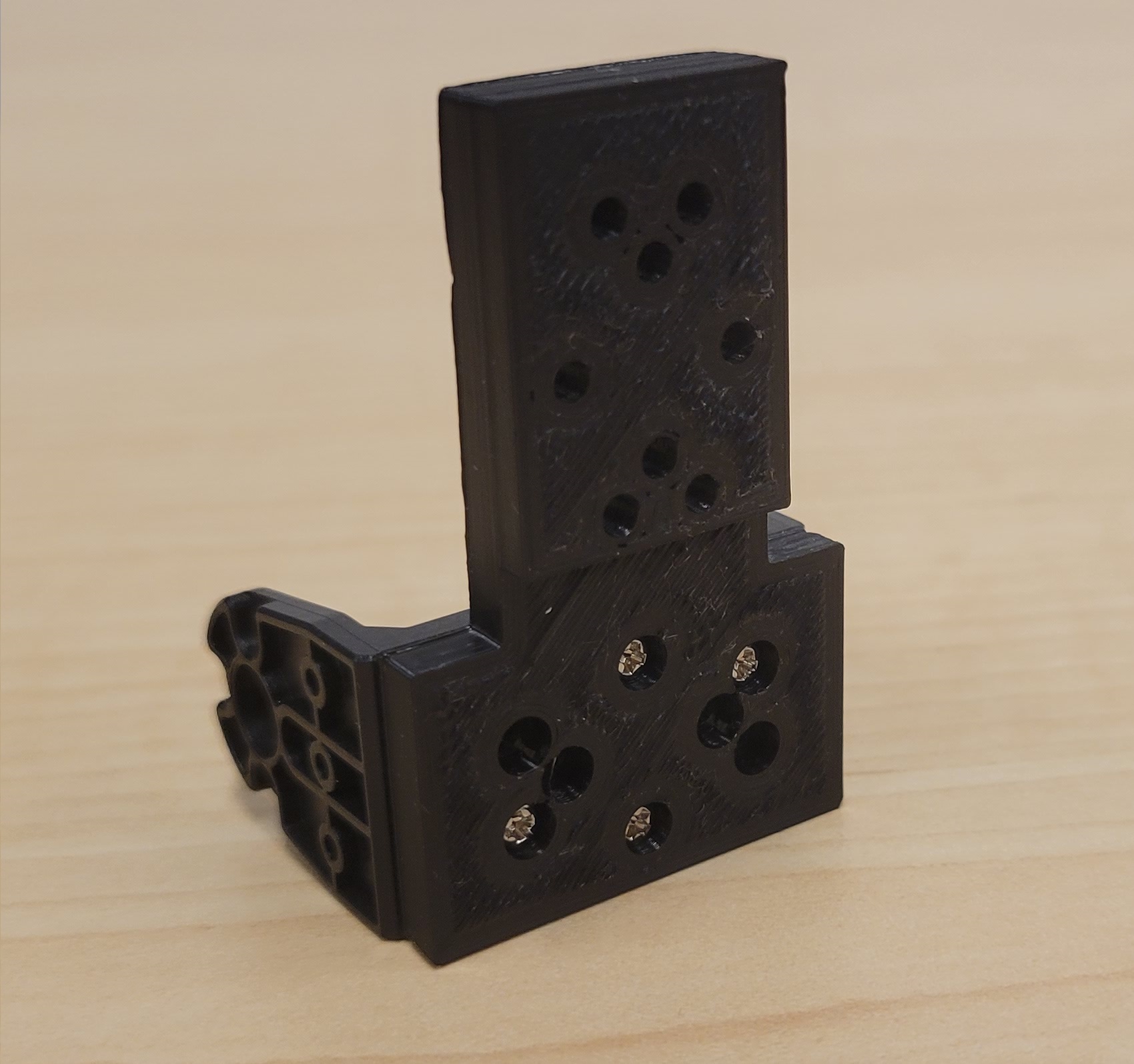
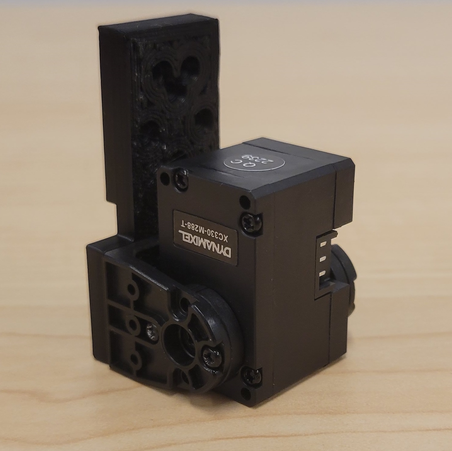
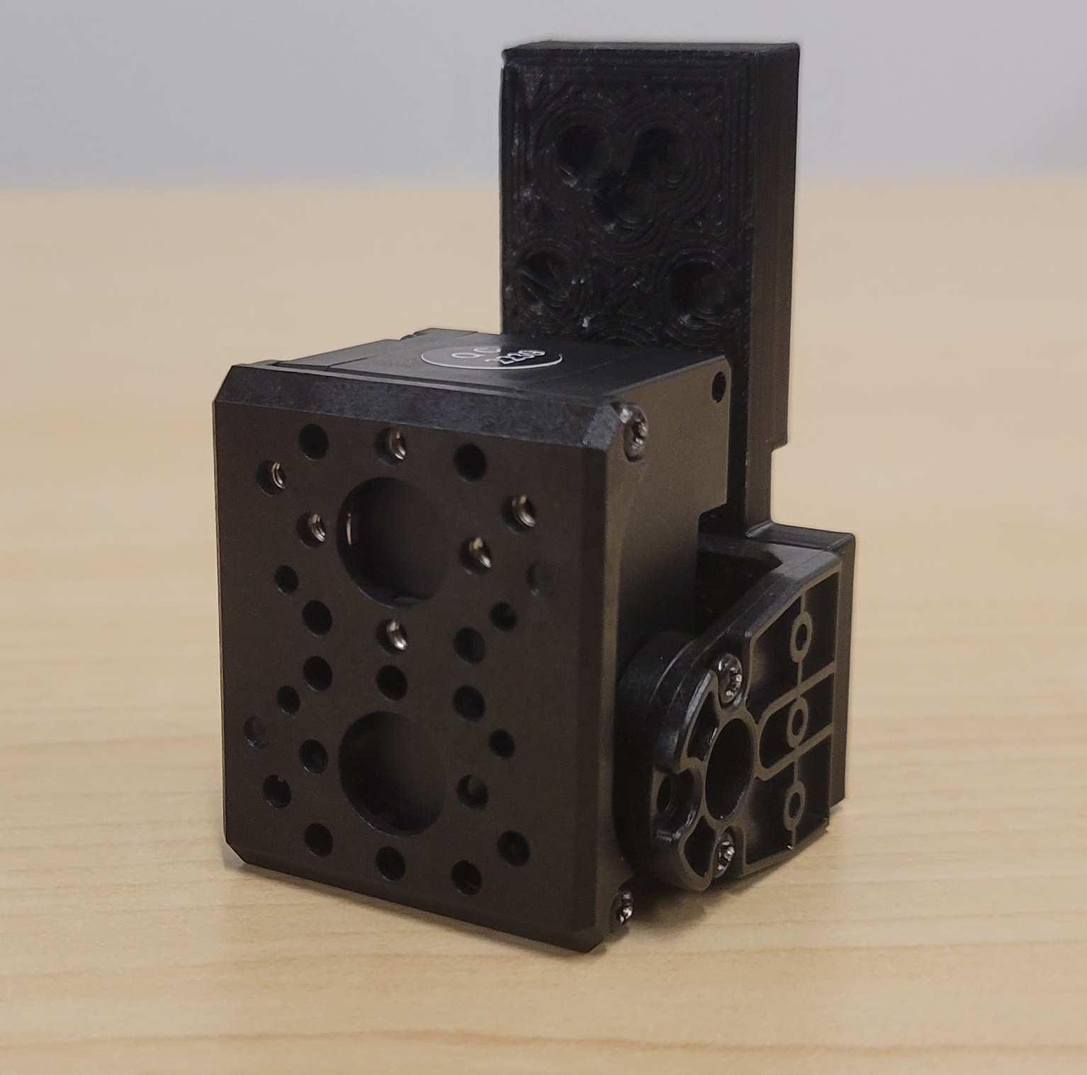
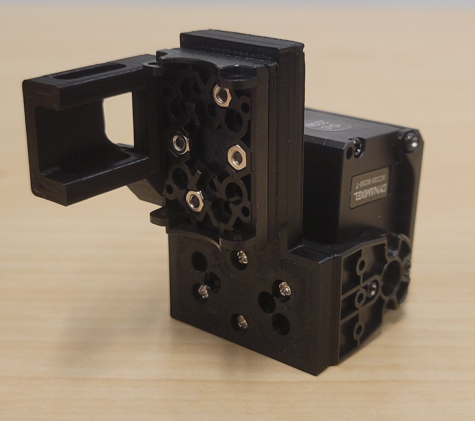
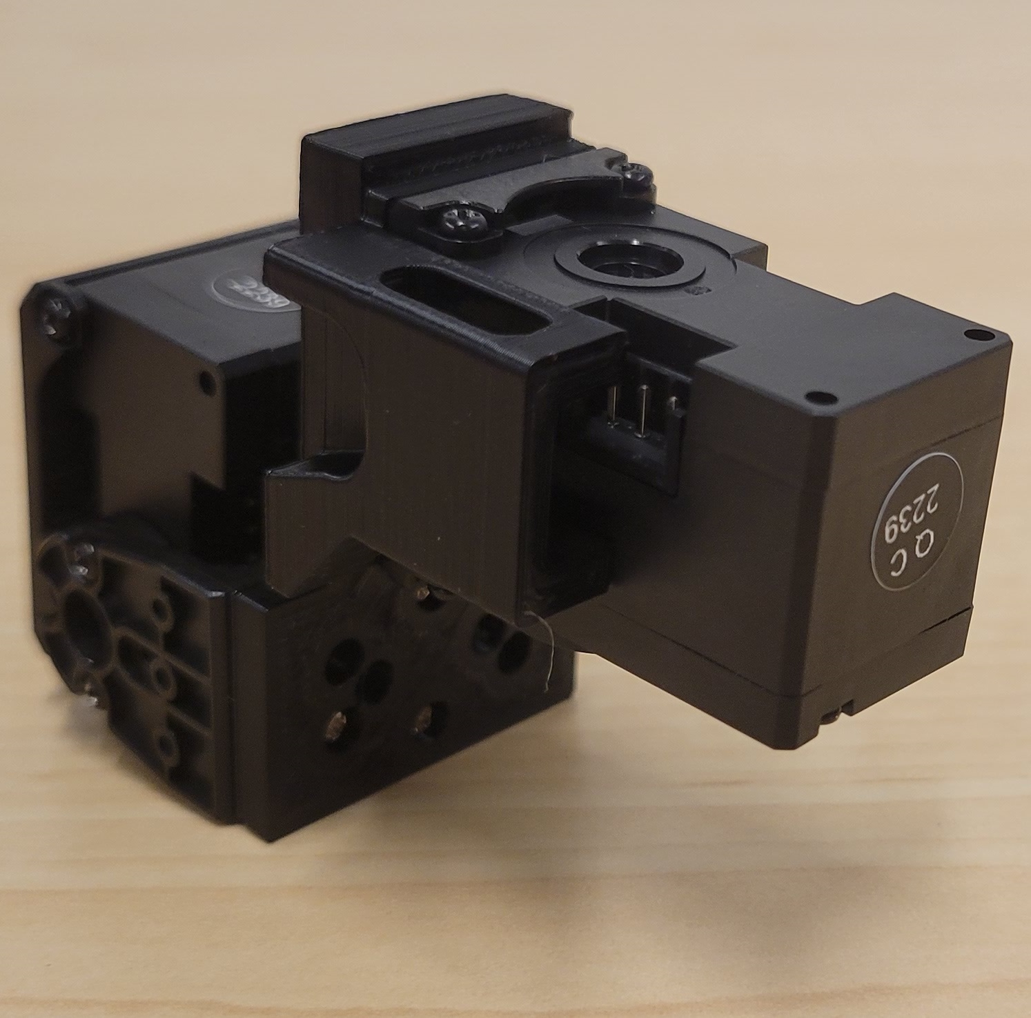
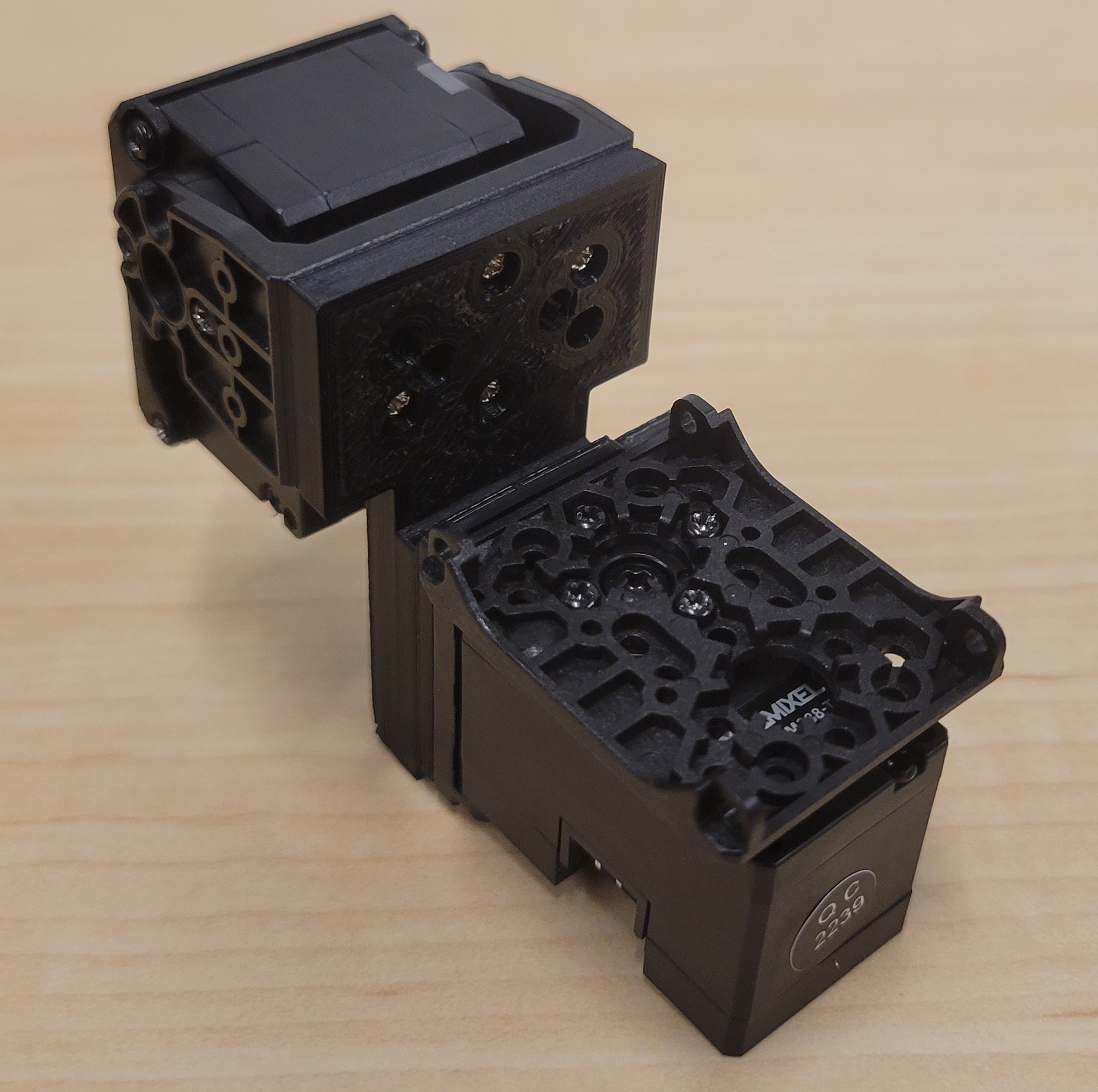
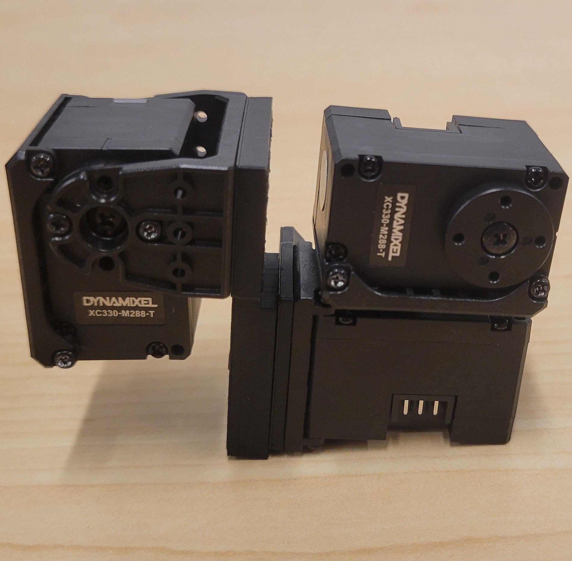
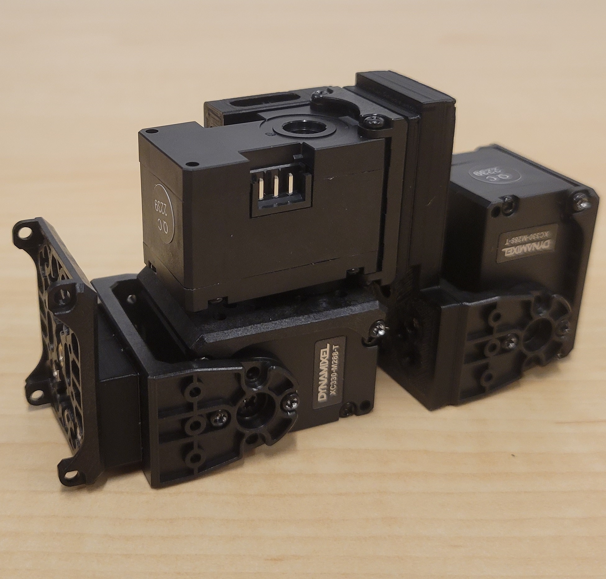
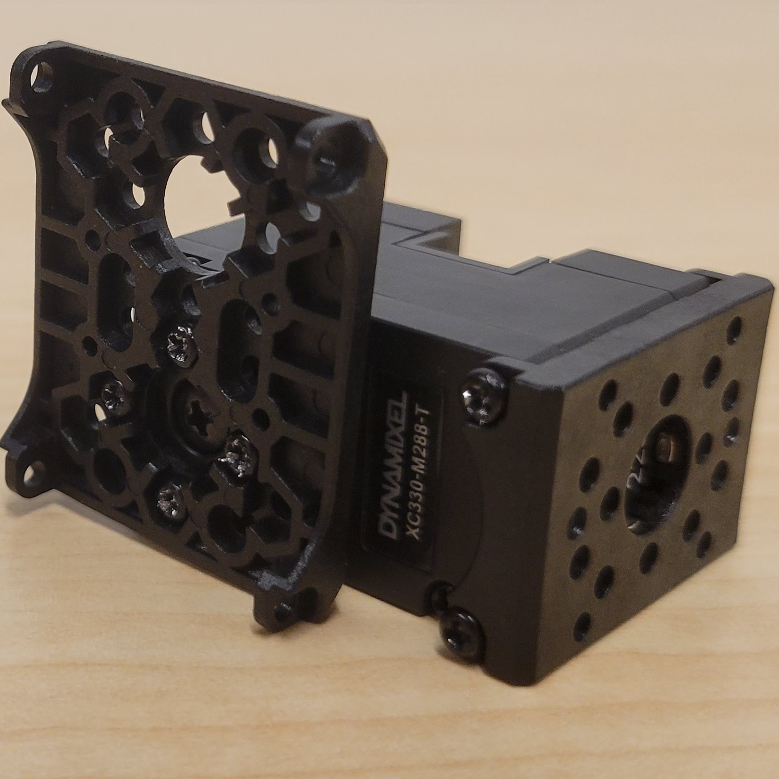
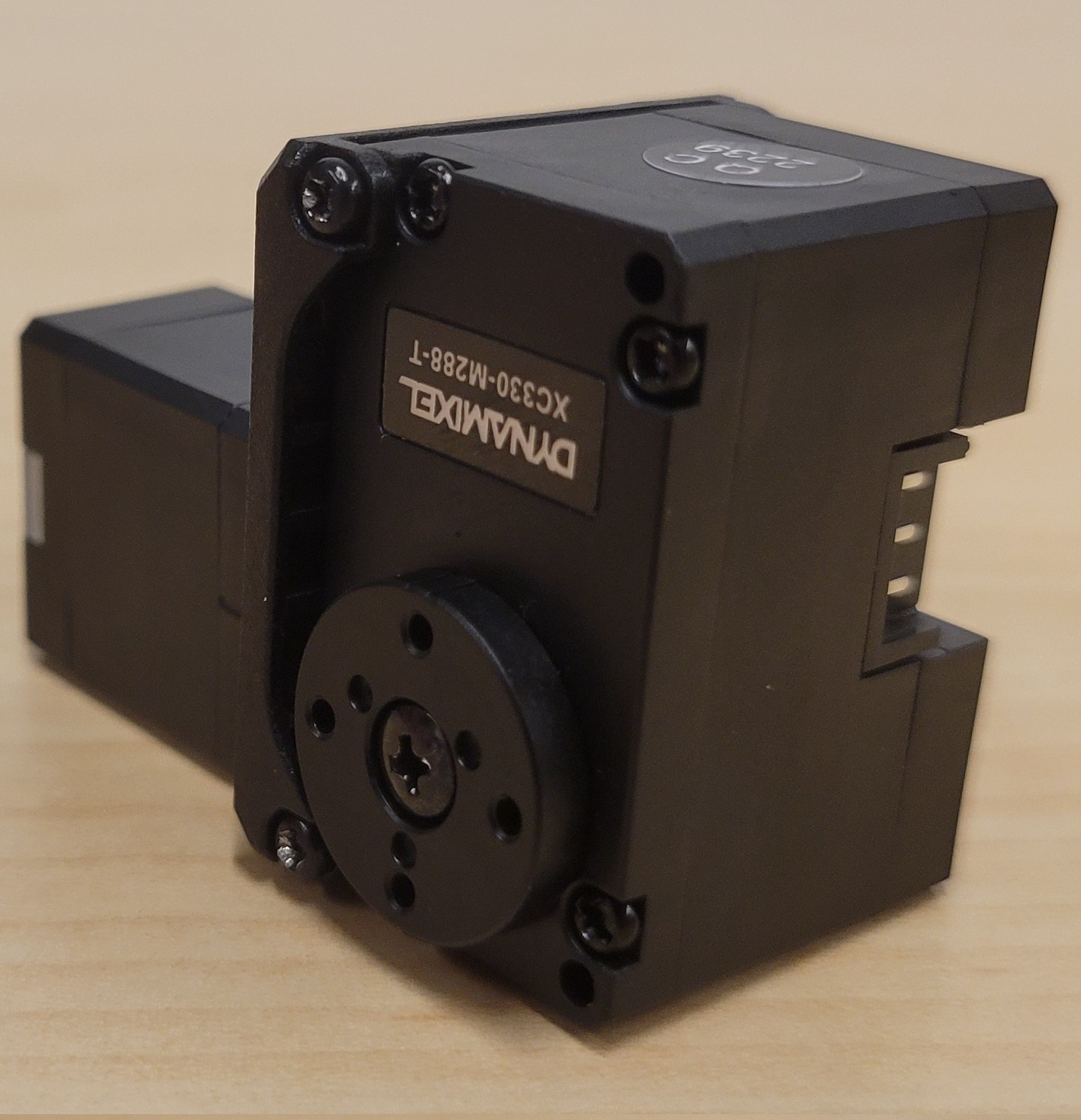
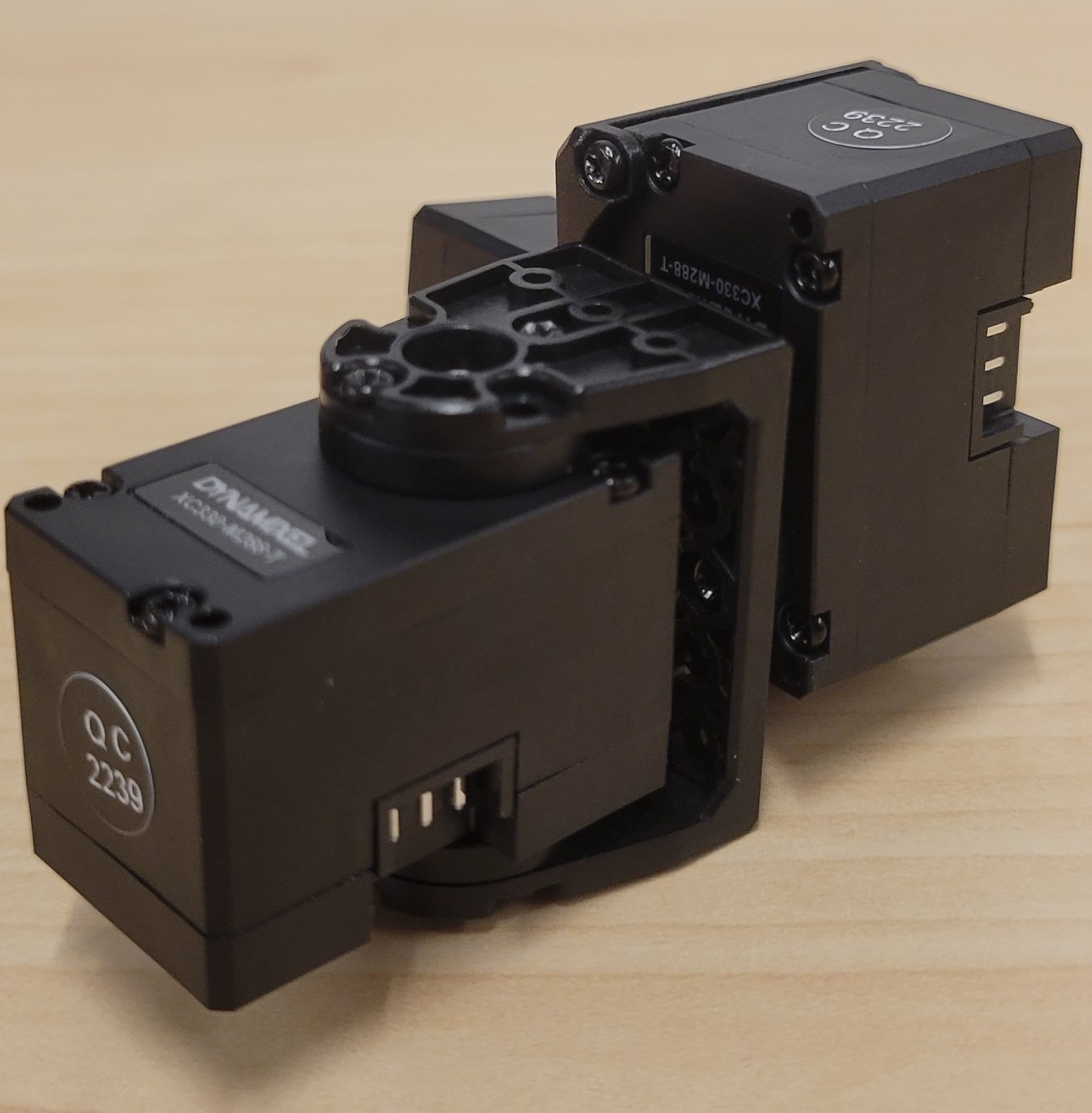
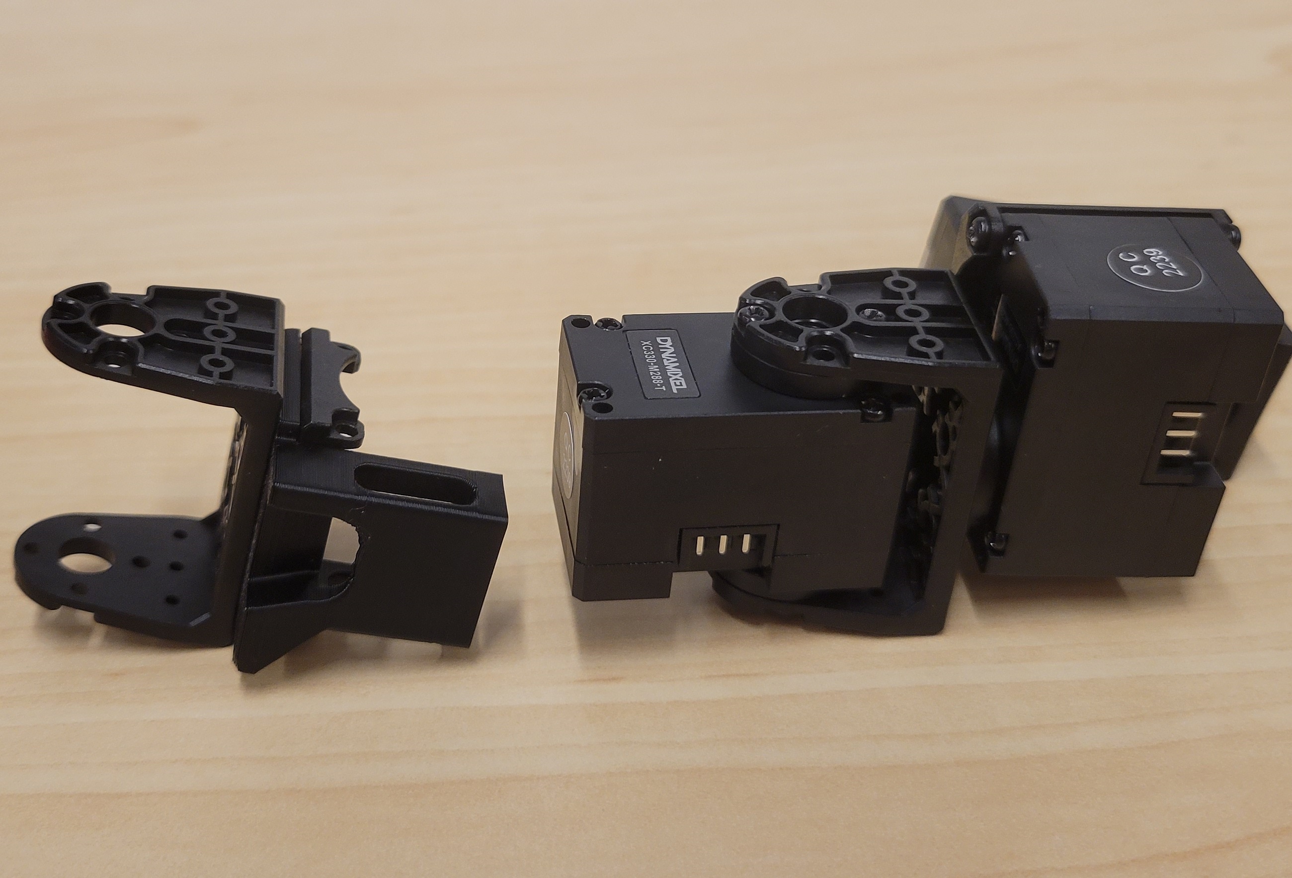
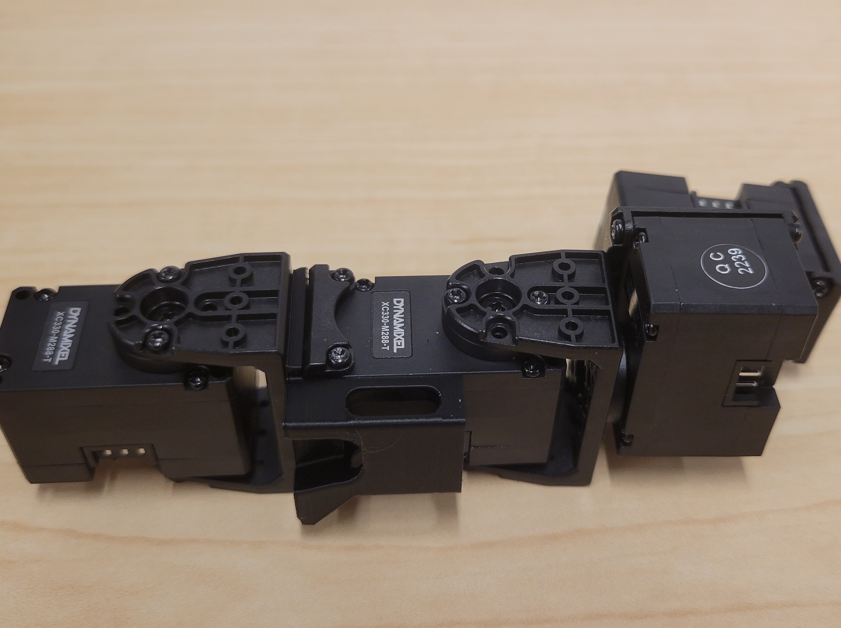
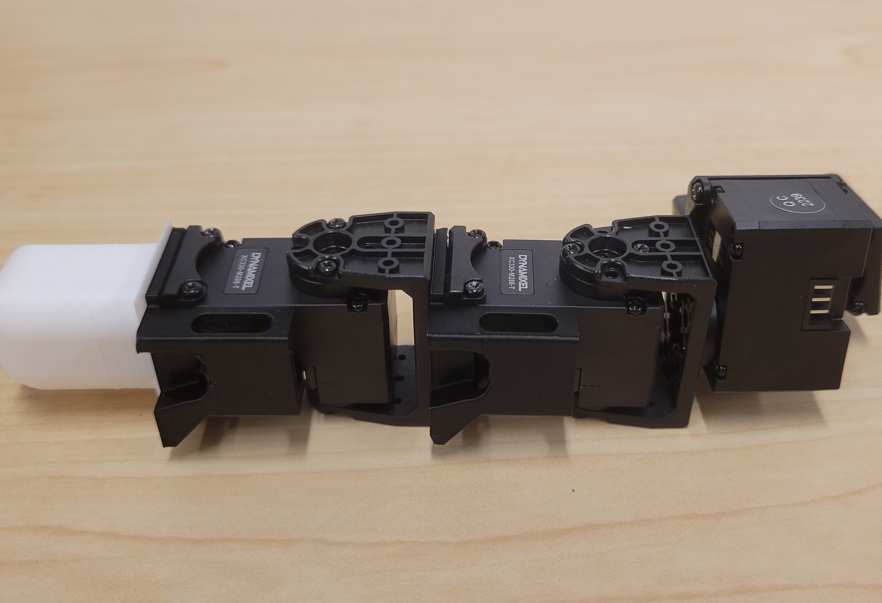
1) This is the Home pose (180 deg.) of the dynamixel, see dots on the horn. They are usually shipped this way. Make sure the parts are attached so that the motors going to the home pose makes the hand go to the home position as in the CAD above.

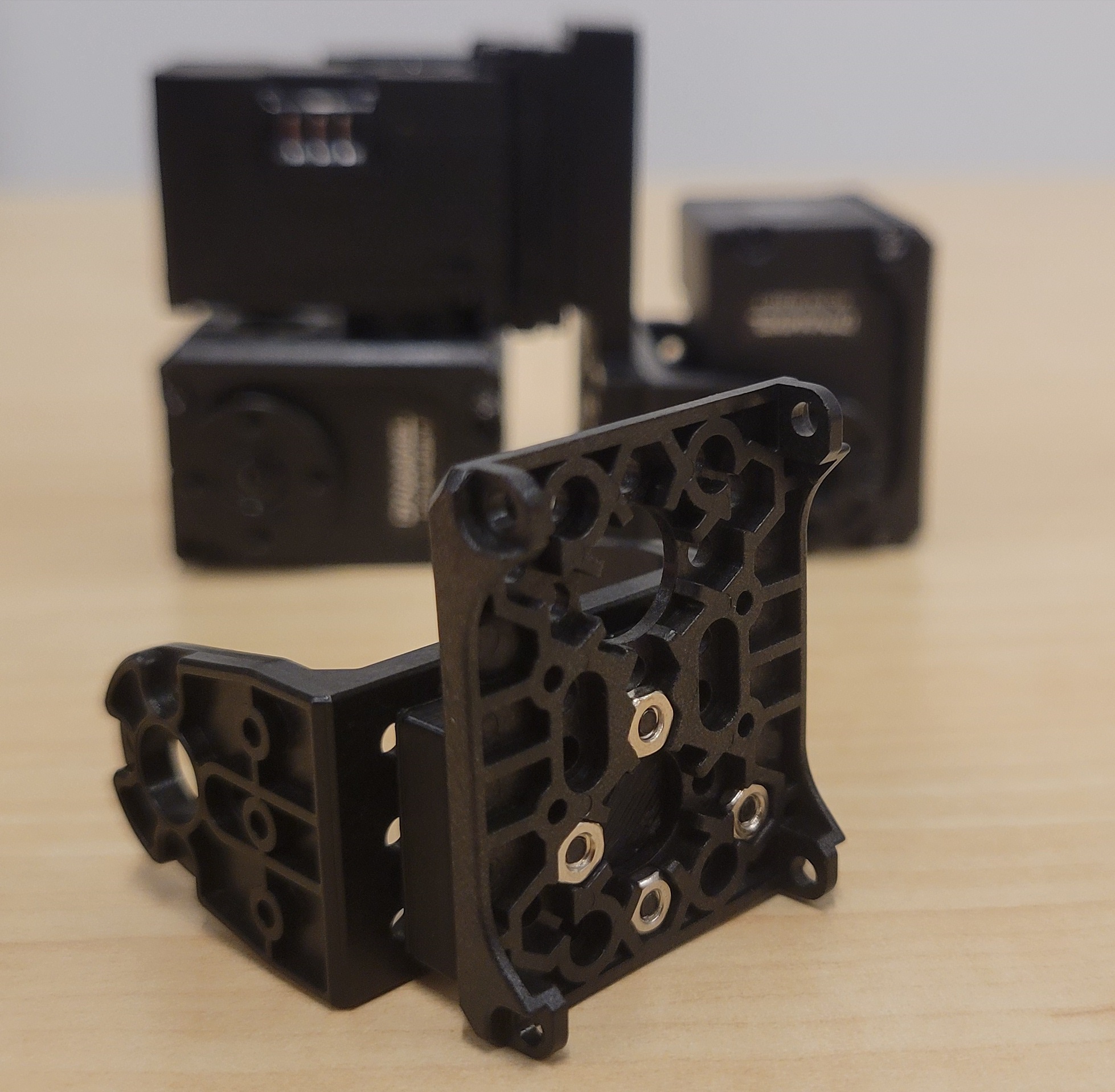
2) Pay attention to the types of screws. "TAP" screws are phillips head, have a serrated edge, and come with the Dynamixel brackets. The other ones are regular hex head. M2/M3 stands for the diameter of the screw and the second number is the length.

MCP Assembly

3D Model Preview:

PIP and DIP Assembly

3D Model Preview:


Repeat three times to create three fingers as below:

Thumb Assembly

3D Model Preview:
For the left hand, attach the S101 in step two
the opposite way around compared to the right hand thumb.

Assemble Palm and Setup Electronics

  • 1) Attach each of the 4 fingers using (4x) M2 8mm screws.
  • 2) Insert M3 6mm Brass Inserts (5x) with soldering iron at 250 °C into the palm. Also insert them into a mounting lid of your choice.
  • 3) ID Motors one by one using Dynamixel Wizard. Note, the MCP side motors are 0,4,8.
  • 4) Chain all of the motors together. If you are using the optional custom cable, connect each finger and the U2D2 to the custom cable. If not, use the Dynamixel Power Hub to improvise and connect everything together.